N2x B58TU (HDP6) HPFP Install DIY
This guide is intended for those that want to install the B58TU HPFP themselves.
No affiliation with any sources in this guide, this guide is designed to be purely instructional for DIY/DYO people.
Please note! The HPFP Screws should be replaced on install as they are Torque To Yield bolts. This means they are a 1x use bolt.
Video References
5 Series DIY Install Video
A community member's DIY video - the install on 5 Series is different from other F series cars.
Kies Motorsports N55 Install Guide
Key takeaway: LPFP feed line connection and wiring harness modification for pre 11/2014 cars.
Installation Steps
Step 1: Remove Engine Covers
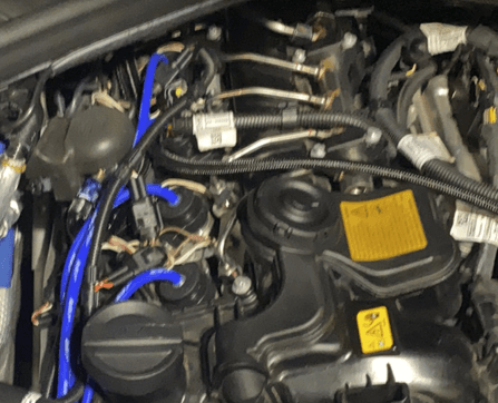
Remove the engine bay beauty covers to expose the HPFP and give you more room to work in, disconnect the battery (do not close your boot/trunk). Proceed to remove the fuel lines - be careful that these lines will have pressurised fuel in them. It is advised to place a heavy rag or cloth over the connection as you undo it SLOWLY so the cloth/rag soaks up the excess fuel. Be sure to wipe away any excess fuel as this can cause a fire if it gets onto the exhaust manifold.
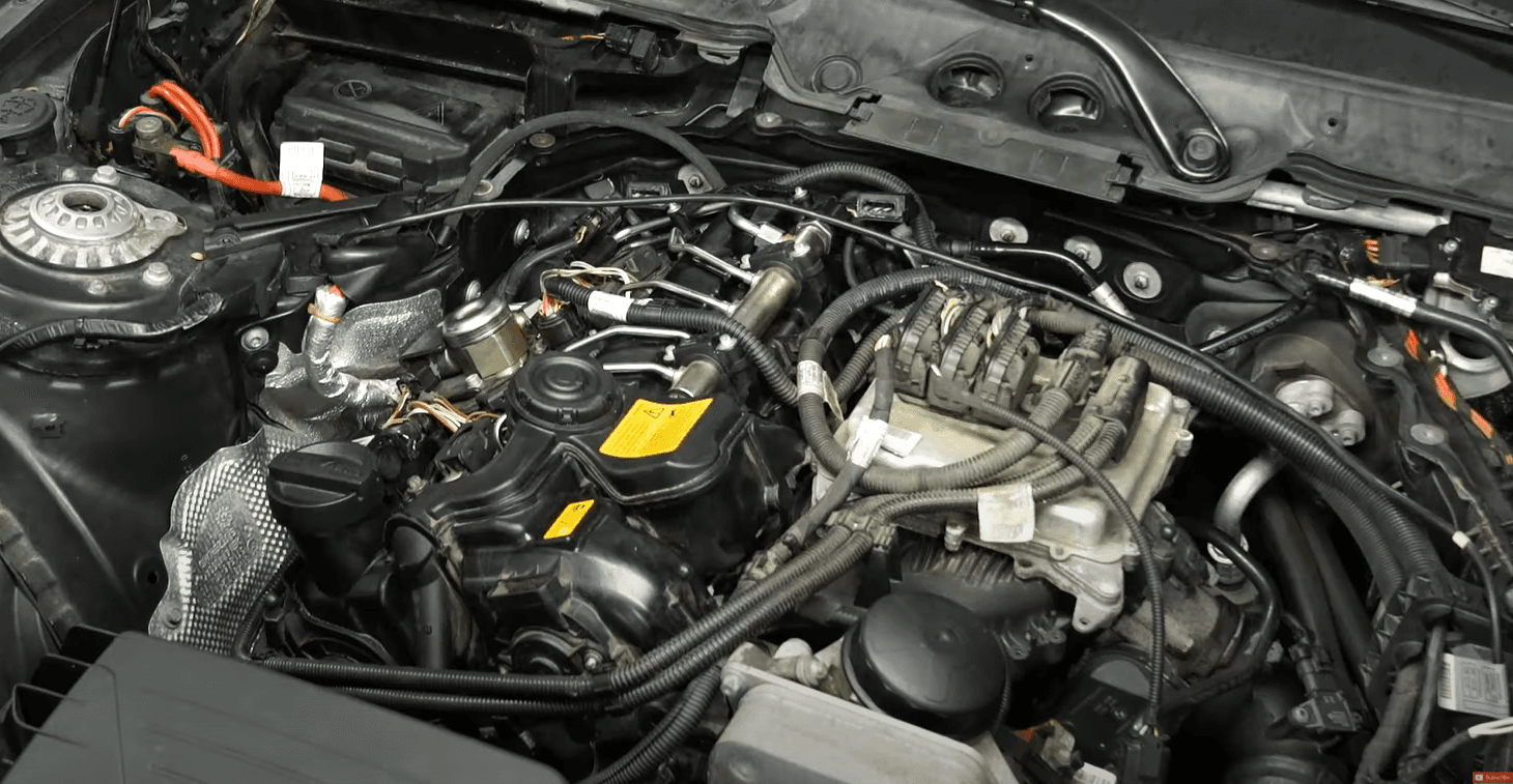
Step 2: Remove the HPFP
Begin removing the HPFP, be careful to not allow dirt and debris to get into the HPFP housing as this will get into the engine and affect its operation.
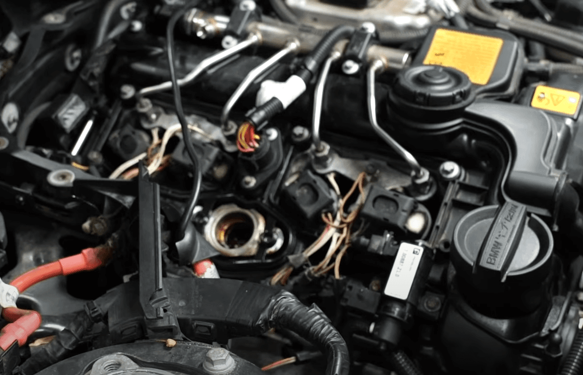
Step 3: Route the LPFP Feed Line
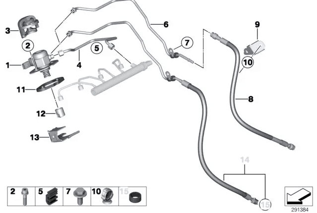
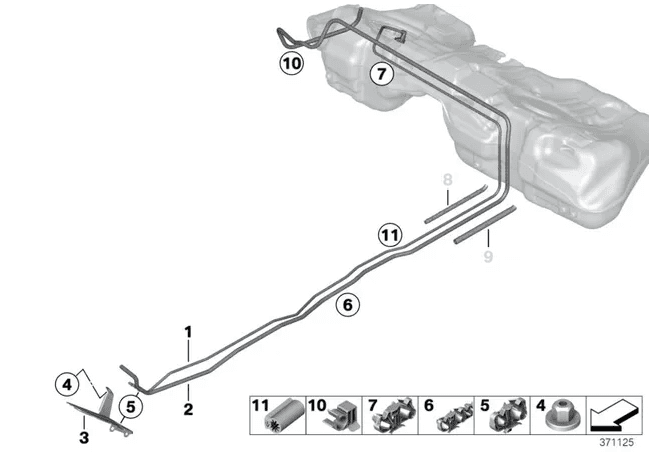
You will be connecting the LPFP Feedline to the end of the 1 piece LPFP feedline from the fuel tank, completely replacing the rubber fuel hose that is located at the gearbox/firewall. What this means is the fuel line that comes from the fuel tank to the gearbox area will remain and the hose from the gearbox area to the engine will be replaced. Access to this hose is limited and can be tight, if you are struggling you will need to look at removing the intake manifold however be careful to not let dirt and debris enter the intake ports of the cylinder head.
Step 4: Disconnect Quick Release Fittings
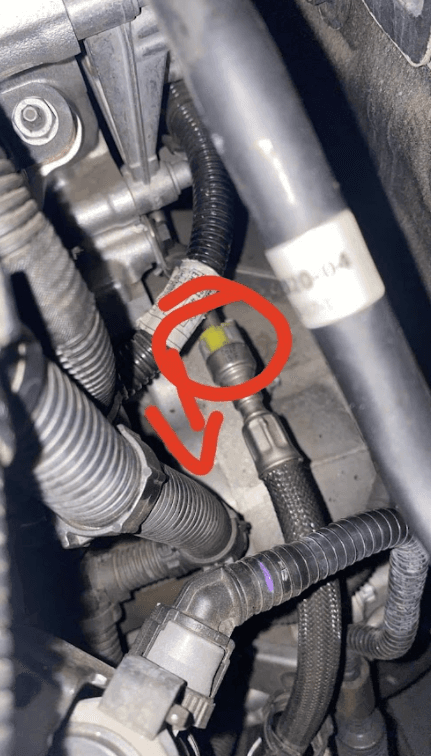
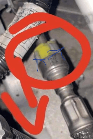
The Rubber LPFP Feedline uses quick disconnect fittings. Some cars may have a grey lock clip that prevents the yellow push release mechanism from being pushed down - please remove this, then proceed to push the yellow clip down and slowly remove the hard/solid LPFP feedlines from either ends.
Step 5: Remove Rubber Hose
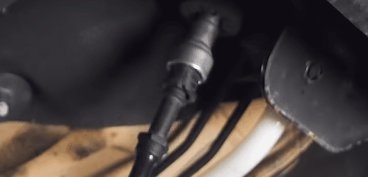
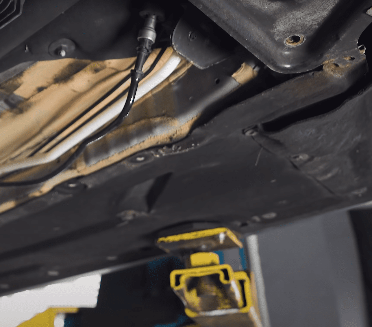
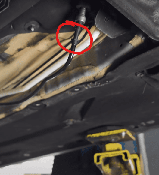
You should now be presented with the following, now reach down and undo the black rubber hose from the other end (if this is too hard, you may find it easier to do under the car).
The kit is designed to be connected to the hose fitting circled in red below, however whilst the hose is long enough to route to the actual fuel tank it lacks the proper 90 deg fitting to connect to the LPFP bucket — if you want to connect directly to the tank a -6AN male to male fitting is required.
Step 6: Route New Fuel Hose
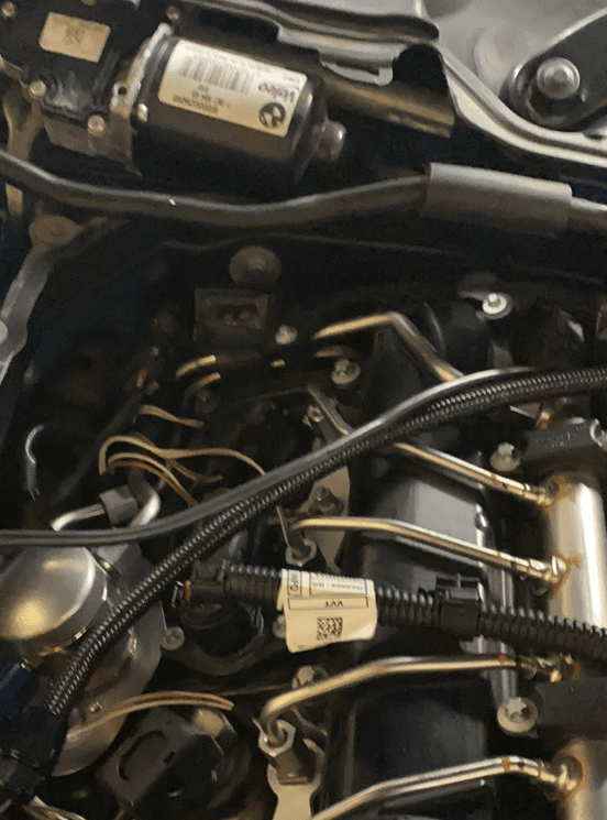
Route the new fuel hose to the HPFP. DO NOT route the fuel hose close to the exhaust manifold - route the hose over the intake manifold in a neat fashion. This hose cannot withstand more than 150°C temperature which the exhaust side of the engine will and can exceed.
Step 7: Modify Valvetronic Seal Plate
Remove the factory Valvetronic Seal plate and either install the modified one or modify your current one as below. Modifying can be done by sanding the end of it down until the brass is almost exposed.
Step 8: Install the New B58TU HPFP
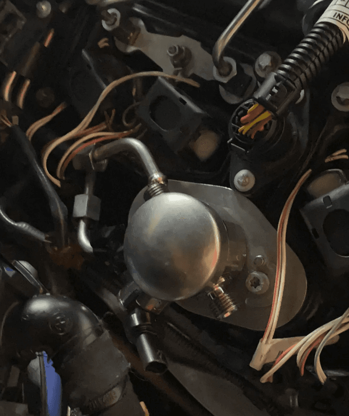
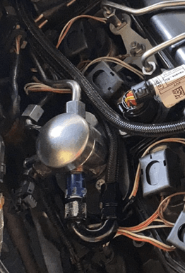
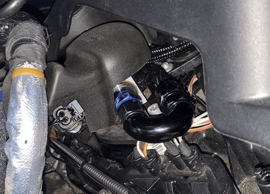
Install the new B58TU (HDP6) HPFP, take note of the orientation of the electrical connector. Should you have the electrical connector facing the intake manifold (opposite to the photo below), you will then have the inlet (LPFP) and outlet (HPFP Fuel Rail) around the wrong way. It is important that the electrical connector is in the same position as the stock location or as per the below photo.
Step 9: Torque the Bolts
The tightening torque of the bolts on the HPFP is 12Nm. It is strongly advised you use a torque wrench to do this.
Step 10: Test for Leaks
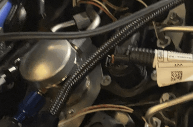
Your end result should now look something like this. Ensure you test your system for leaks before reinstalling all auxiliaries. This can be done by reconnecting the battery, and either locking, unlocking the vehicle or starting the vehicle ignition. Doing this will turn the LPFP on and prime the fuel line.
Wiring Harness Modification for Vehicles Before 11/2014
Differences between plugs on the pre 11/2014 (left) and post 11/2014 (right):

Modification Steps
Step 1: Clip the old plug off of the harness in the engine bay and crimp on the new connector. Clip the excess harness off of the new plug before attaching it to the engine harness.
Slide some heat shrink onto each wire, then connect:
- White with green stripe → Red wire
- White wire → White wire
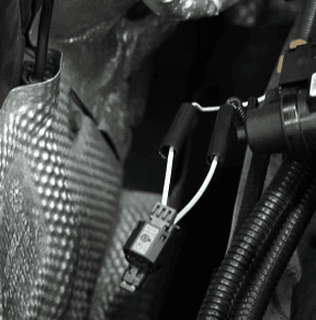
Use a lighter, match or heat gun to "shrink" the heat shrink over the wiring connector to ensure it is water tight. Alternatively you can use electrical crimp connectors but you must ensure the connections are good.
Important: If the modification process to the wiring is not good (should have 0 resistance either side of the connection) then the pump will fail to work properly.